EXPOSED / LAY-IN CEILING SYSTEM
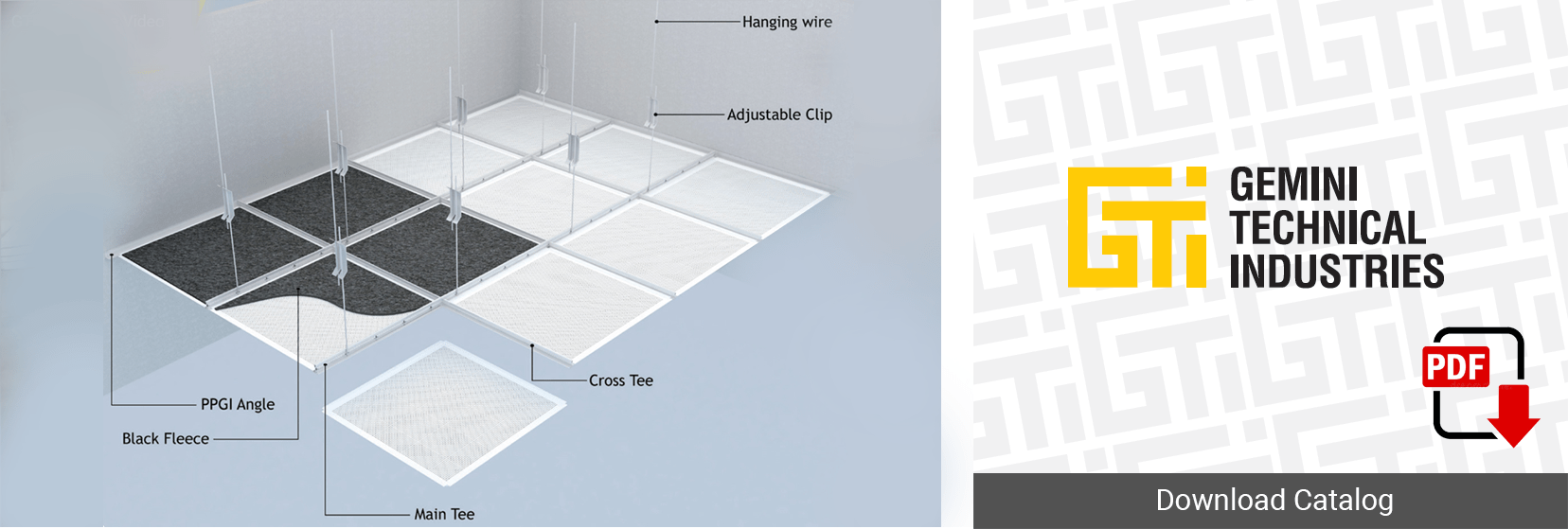
The GTI Exposed Ceiling Suspension System is a structural suspension system for Lay – In Ceiling Panels. It consists of 24mm/15mm Main Channel and cross tee that combine superior load-carrying capacity, exceptional stability and design flexibility. The GTI Exposed Ceiling System save time and money as its offers an easy approach to installations and with the special stitch design in GTI Tees that give more strength for the system and rigidity.
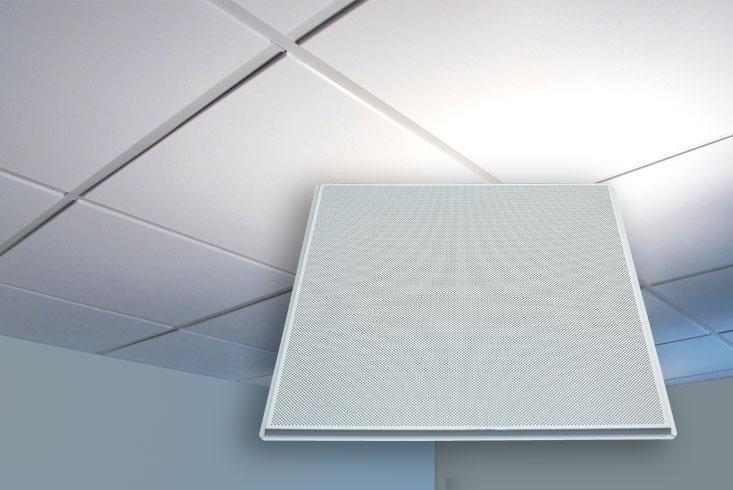
Manufactured from steel and aluminum, the tiles can either be plain or perforated and are commonly painted, pre-coated and powder coated. If perforated, the holes can be in a straight or diagonal patterns with different designs.
Applications, Features & Benefits
| APPLICATIONS | FEATURES & BENEFITS |
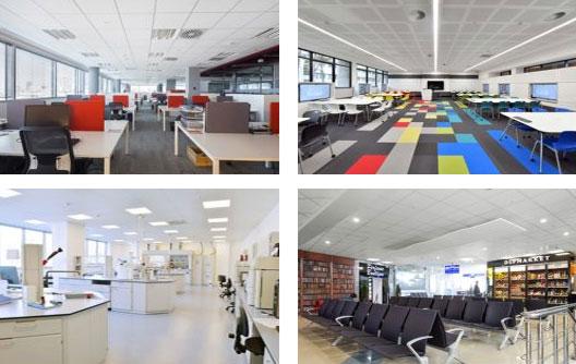
| Offices | Choice of tile edge detail |
| Classrooms | Standard sizes ex-stock |
| Laboratories | Ceiling takes up minimal void space |
| Hospitals | Simple downward access |
| Airports | Services easily integrated |
| Other commercial installations | Excellent fire performance |
Plain, Perforated, and others are available
| Reference/ID | Dimensions (mm) | Thickness (mm) | Color |
| GLIT-243060 GLIT-253060 | 300 x 600 | 0.6/0.7/0.8 | RAL-9003/ RAL- 9010 |
| GLIT-2430120 GLIT-2530120 | 300 x 1200 | 0.6/0.7/0.8 | RAL-9003/ RAL- 9010 |
| GLIT-246060 GLIT-256060 | 600 x 600 | 0.6/0.7/0.8 | RAL-9003/ RAL- 9010 |
| GLIT-2460120 GLIT-2560120 | 600 x 1200 | 0.6/0.7/0.8 | RAL-9003/ RAL- 9010 |
Finish Coating / Material Standard
The coating on the tiles conform to ECCA standards and performed as per European norms: EN 1396 specifications. Aluminum alloy / temper:3005 / 3105 – H24, as per ASTM B 209 M.
Fire Classification
Class 1 Surface spread of flame as per BS 476: Part 7: 1997
Class A Surface spread of flame as per ASTM E84-16
Note: Lay-In Tile on T15 and T24 available.
Raw Material
Aluminum Alloy as per ASTM B – 209M / Zinc plated. Galvanized Steel as per ASTM A653M Stainless Steel ( Brush / Mirror ).
Lay-In-Suspension System Components
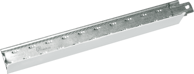
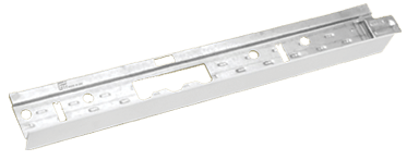
The Suspension T-Grid with a capping face used for 600mm x 600mm aluminium, steel, vinyl or mineral fibre tiles.
| Description | Reference/ID | Dimensions(mm) | Thickness | Leghth(mm) | Color |
| Cross Tee |
GTICT60 GTICT120 GTICT1560 GTICT15120 |
25 x 24 (T-24) 25 x 24 (T-24) 32 x 15 (T-15) 32 x 15 (T-15) |
600 1200 600 1200 |
RAL-9003/RAL-9010 RAL-9003/RAL-9010 RAL-9003/RAL-9010 RAL-9003/RAL-9010 |
|
| Main Tee |
GTIMT360 GTIMT360 GTIPPGA15 |
32 x 15/24 38 x 24 19 x15 (T-15) |
0.45 |
3600 3600 |
RAL-9003/RAL-9010 RAL-9003/RAL-9010 |
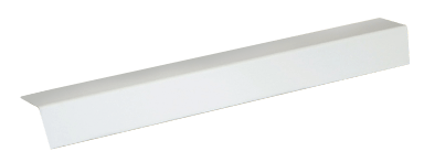
| L-Angle |
GTIPPGA20 GTIPPGA25 |
20 x 20 25 x 25 |
0.45 0.45 |
3000 3000 |
RAL-9003/RAL-9010 RAL-9003/RAL-9010 |
| L-Angle with Tab | GTITA25 | 25 x25 | 0.45 | 3000 | |
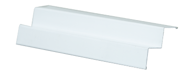
| W-Angle |
GTIWA10 GTIWA15 GTIWA20 |
A - B - C - D 19 -9- 9- 19 19 -15 -15- 19 20- 19- 19-20 |
0.45 0.45 0.45 |
3000 3000 3000 |
RAL-9003/RAL-9010 RAL-9003/RAL-9010 |
| W-Angle with Tab |
GTIWA10T GTIWA15T GTIWA20T |
A- B- C- D 19- 9- 9- 19 19- 15- 15- 19 20- 19- 19- 20 |
0.45 0.45 0.45 |
3000 3000 3000 |
RAL-9003/RAL-9010 RAL-9003/RAL-9010 |
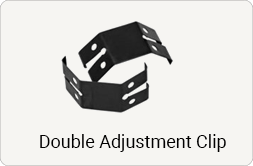
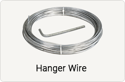
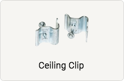
ACCESSORIES
Installation
Installation Steps
Step 1
Mark the wall
Using the water level or laser method, mark the desired height on the wall.
Step 2
Attach the L-Angle / L or W shape
Using screws and nails, fix the L-Angle on the walls at the marked height.
Step 3
Complete the grid
Mark the required distance intervals then proceed to fix the suspension system using the Main and Cross Tee according to the approved layout.
Step 4
Attach the Wires
Fix the suspension system with 3mm or 4mm wires using ceiling clips and cartridges or wedge anchor.
Step 5
Install the tiles
Lay in the 595mm x 595mm tiles in the correct pattern.
Step 6
Cut the tiles (if necessary)
Cut apertures for lights and other services where required.
Features

